================================================================================ NETCAD CCNA 200-301 STUDY GUIDE: SPANNING TREE PROTOCOL (STP) Topic: Layer 2 Loop Prevention, Root Bridge Elections, Port Roles & Verification Resource Portal: https://www.netcad.company
- INTRODUCTION & THE REDUNDANCY DILEMMA
In enterprise campus networks, high availability is mandatory. Network engineers design redundant physical connections between switches (using triangular or mesh topologies) so that if one cable or switch fails, traffic can immediately failover to an alternate path.
However, Layer 2 Ethernet switches present a serious vulnerability when connected in redundant loops:
-
No Layer 2 Time-to-Live (TTL): At Layer 3, IP packets include a TTL field. Every router decrements this value by 1; if TTL reaches 0, the packet drops. Ethernet frame headers DO NOT have a TTL field. Once an Ethernet frame enters an unmanaged physical loop, switches will circulate and multiply that frame endlessly.
-
The Three Major Layer 2 Loop Catastrophes:
- Broadcast Storms: Broadcast frames (ARP Requests, DHCP Discovers) are flooded out of all ports except the port where they arrived. In a loop, broadcasts multiply exponentially, consuming 100% of bandwidth and pegging switch CPU to 100%, crashing the LAN.
- MAC Database Instability (CAM Table Thrashing): Because the same frame arrives on multiple interfaces in rapid succession, the switch constantly overwrites its MAC address table (CAM table) with conflicting port mappings. Unicast forwarding fails completely.
- Duplicate Frame Copies: End hosts receive repeated copies of the same data frame, corrupting TCP/UDP sessions and application stacks.
- THE STP SOLUTION: PHYSICAL LOOPS VS. LOGICAL TOPOLOGY
Spanning Tree Protocol (STP), standardized under IEEE 802.1D and refined in IEEE 802.1w (Rapid STP), solves this problem dynamically:
- Physical Topology: Fully redundant physical links remain cabled and ready.
- Logical Topology: STP calculates a loop-free tree structure and places redundant interfaces into a Blocking (Discarding) state.
- Automatic Failover: If an active forwarding link fails, STP detects the topology change and transitions the blocked backup interface into Forwarding automatically.
- BRIDGE PROTOCOL DATA UNITS (BPDUs)
Switches elect roles and detect loops by exchanging Layer 2 control packets called Bridge Protocol Data Units (BPDUs).
- Configuration BPDUs: Sent every 2 seconds (default Hello Time) by the Root Bridge and relayed downstream by all switches to maintain topology information.
- Topology Change Notification (TCN) BPDUs: Sent by a switch when a port transitions up or down to inform the Root Bridge, which then instructs all switches to temporarily lower their MAC address aging time from 300 seconds down to 15 seconds (Forward Delay).
- Multicast Destination: BPDUs are transmitted to the reserved multicast MAC address: 01:80:C2:00:00:00.
- THE BRIDGE ID (BID) STRUCTURE & CISCO PVST+
Every switch running STP has a unique 8-byte (64-bit) Bridge Identifier (BID):
+------------------------------------------------------------------------------+ | Priority Field (2 Bytes / 16 Bits) | Base MAC Address (6 Bytes / 48 Bits) | +------------------------------------------------------------------------------+
In Cisco networks, Per-VLAN Spanning Tree Plus (PVST+) splits the 16-bit priority field into two pieces:
- 4-Bit Priority Multiplier: Configurable in strict multiples of 4096 (0, 4096, 8192, 12288, 16384, 20480, 24576, 28672, 32768, etc.).
- 12-Bit System ID Extension: Stores the exact VLAN ID (1 to 4094).
Default Cisco Switch Bridge Priority Calculation:
- Default Configured Priority = 32,768
- System ID Extension (VLAN 1) = 1
- Total Advertised Priority = 32,768 + 1 = 32,769
- THE 3-STEP STP ELECTION PROCESS
Whenever switches boot up or a topology change occurs, STP executes three sequential decision steps:
================================================================================ STEP 1: ELECTION OF THE ROOT BRIDGE
There is exactly ONE Root Bridge per VLAN. The Root Bridge acts as the central reference point and master switch of the logical tree.
The switch with the LOWEST Bridge ID (BID) wins:
- Lowest Priority Wins: Switches compare priorities. If one switch is configured with a lower priority (e.g., 24577 vs. 32769), that switch immediately wins the election.
- Lowest MAC Address Breaks the Tie: Because all out-of-the-box Cisco switches share the default priority 32,769, the priority almost always ties! The switch with the lowest hexadecimal MAC address becomes the Root Bridge.
Hexadecimal MAC Comparison Rule: MAC addresses are evaluated character-by-character from left to right: 0 < 1 < 2 < 3 < 4 < 5 < 6 < 7 < 8 < 9 < A < B < C < D < E < F (0 is lowest, F is highest).
ROOT BRIDGE GOLDEN RULE: All active operational ports on the Root Bridge become Designated Ports (DP). The Root Bridge NEVER blocks any of its own ports!
================================================================================ STEP 2: SELECTION OF ROOT PORTS (RP) ON NON-ROOT SWITCHES
Every Non-Root Switch must choose exactly ONE Root Port (RP).
- Definition: The Root Port is the local interface providing the lowest cumulative Root Path Cost back to the Root Bridge.
- Port State: Root Ports always operate in the Forwarding state.
Standard IEEE STP Port Costs (Inversely proportional to bandwidth):
- 10 Mbps (Ethernet) : Cost = 100
- 100 Mbps (Fast Ethernet) : Cost = 19
- 1 Gbps (Gigabit Ethernet) : Cost = 4
- 10 Gbps (10-Gigabit) : Cost = 2
Tie-Breaking Logic for Root Ports: If a switch has multiple equal-cost links to the Root Bridge, it breaks the tie in this strict order:
- Lowest Cumulative Root Path Cost
- Lowest Sender Bridge ID (Neighbor's BID)
- Lowest Sender Port Priority (Default 128)
- Lowest Sender Internal Port ID (e.g., Fa0/1 beats Fa0/2)
================================================================================ STEP 3: SELECTION OF DESIGNATED PORTS (DP) & BLOCKED PORTS (BP)
Every physical link segment between two switches must have exactly ONE Designated Port (DP) that forwards traffic.
Port Relationship Rules:
- Root Port (RP) <----------> Designated Port (DP)
- Designated Port (DP) <----> Root Port (RP) OR Blocked Port (BP)
Selecting the Blocked Port: On the link between two non-root switches, both switches compete for the DP:
- The switch with the lowest Root Path Cost wins the Designated Port.
- If path costs are equal, the switch with the lower Bridge ID (Lowest Priority, then Lowest MAC) wins the Designated Port.
- The remaining interface on the losing switch becomes the Blocked Port (Alternate Port). It ceases forwarding data frames and learning MAC addresses, effectively breaking the loop!
- CLASSIC IEEE 802.1D PORT STATES & TIMERS
Legacy 802.1D transitions ports slowly through multiple states to guarantee that no temporary loops occur during recalculations:
- Blocking (Discarding): No data forwarded. No MAC addresses learned. Receives BPDUs only. (Waits 20 seconds Max Age if a link failure occurs).
- Listening: No data forwarded. No MAC addresses learned. Transmits and receives BPDUs. (Duration: 15 seconds Forward Delay).
- Learning: No data forwarded. LEARNS source MAC addresses and populates the CAM table. (Duration: 15 seconds Forward Delay).
- Forwarding: Full normal operation. Forwards data frames, updates MAC table, processes BPDUs.
- Disabled: Administratively shut down (shutdown command).
Total Convergence Time: 20s (Max Age) + 15s (Listening) + 15s (Learning) = 50 SECONDS to recover from an indirect link failure in legacy 802.1D STP.
- RAPID SPANNING TREE PROTOCOL (RSTP / IEEE 802.1w)
Modern enterprise networks use Rapid STP (RSTP / 802.1w) or Cisco Rapid PVST+.
- Convergence Time: Sub-second (typically under 1 to 2 seconds).
- Mechanism: Bypasses 30-second listening/learning delays using an active Proposal/Agreement handshake between switches.
- Simplified Port States: Discarding, Learning, and Forwarding.
- Port Roles: Root Port, Designated Port, Alternate Port (backup to RP), and Backup Port (backup to DP on shared media).
- ESSENTIAL CISCO IOS STP CONFIGURATION & VERIFICATION COMMANDS
--- VERIFICATION COMMANDS ---
! 1. View complete STP status for all VLANs or a specific VLAN Switch# show spanning-tree Switch# show spanning-tree vlan 10
! 2. View summary table of port states and root bridge info Switch# show spanning-tree summary
! 3. Check STP details on a specific interface Switch# show spanning-tree interface gigabitEthernet 0/1
! 4. Identify the active Root Bridge for a VLAN Switch# show spanning-tree vlan 10 root
--- CONFIGURATION COMMANDS ---
! 1. Manually configure switch as Primary Root Bridge (Priority becomes 24576) Switch(config)# spanning-tree vlan 10 root primary
! 2. Configure switch as Secondary Root Bridge (Priority becomes 28672) Switch(config)# spanning-tree vlan 10 root secondary
! 3. Manually set specific priority (Must be a multiple of 4096) Switch(config)# spanning-tree vlan 10 priority 4096
! 4. Switch global mode to Rapid PVST+ (Recommended enterprise standard) Switch(config)# spanning-tree mode rapid-pvst
! 5. Enable PortFast on access ports (Instantly transitions edge ports to Forwarding) Switch(config-if)# spanning-tree portfast
! 6. Enable BPDU Guard on host ports (Protects against rogue switches) Switch(config-if)# spanning-tree bpduguard enable
END OF NETCAD STP STUDY GUIDE • LEARN TODAY. ENGINEER TOMORROW.
NETCAD CCNA 200-301 STUDY GUIDE: SPANNING TREE PROTOCOL (STP) Topic: Layer 2 Loop Prevention, Root Bridge Elections, Port Roles & Verification Resource Portal: https://www.netcad.company
- INTRODUCTION & THE REDUNDANCY DILEMMA
In enterprise campus networks, high availability is mandatory. Network engineers design redundant physical connections between switches (using triangular or mesh topologies) so that if one cable or switch fails, traffic can immediately failover to an alternate path.
However, Layer 2 Ethernet switches present a serious vulnerability when connected in redundant loops:
-
No Layer 2 Time-to-Live (TTL): At Layer 3, IP packets include a TTL field. Every router decrements this value by 1; if TTL reaches 0, the packet drops. Ethernet frame headers DO NOT have a TTL field. Once an Ethernet frame enters an unmanaged physical loop, switches will circulate and multiply that frame endlessly.
-
The Three Major Layer 2 Loop Catastrophes:
- Broadcast Storms: Broadcast frames (ARP Requests, DHCP Discovers) are flooded out of all ports except the port where they arrived. In a loop, broadcasts multiply exponentially, consuming 100% of bandwidth and pegging switch CPU to 100%, crashing the LAN.
- MAC Database Instability (CAM Table Thrashing): Because the same frame arrives on multiple interfaces in rapid succession, the switch constantly overwrites its MAC address table (CAM table) with conflicting port mappings. Unicast forwarding fails completely.
- Duplicate Frame Copies: End hosts receive repeated copies of the same data frame, corrupting TCP/UDP sessions and application stacks.
- THE STP SOLUTION: PHYSICAL LOOPS VS. LOGICAL TOPOLOGY
Spanning Tree Protocol (STP), standardized under IEEE 802.1D and refined in IEEE 802.1w (Rapid STP), solves this problem dynamically:
- Physical Topology: Fully redundant physical links remain cabled and ready.
- Logical Topology: STP calculates a loop-free tree structure and places redundant interfaces into a Blocking (Discarding) state.
- Automatic Failover: If an active forwarding link fails, STP detects the topology change and transitions the blocked backup interface into Forwarding automatically.
- BRIDGE PROTOCOL DATA UNITS (BPDUs)
Switches elect roles and detect loops by exchanging Layer 2 control packets called Bridge Protocol Data Units (BPDUs).
- Configuration BPDUs: Sent every 2 seconds (default Hello Time) by the Root Bridge and relayed downstream by all switches to maintain topology information.
- Topology Change Notification (TCN) BPDUs: Sent by a switch when a port transitions up or down to inform the Root Bridge, which then instructs all switches to temporarily lower their MAC address aging time from 300 seconds down to 15 seconds (Forward Delay).
- Multicast Destination: BPDUs are transmitted to the reserved multicast MAC address: 01:80:C2:00:00:00.
- THE BRIDGE ID (BID) STRUCTURE & CISCO PVST+
Every switch running STP has a unique 8-byte (64-bit) Bridge Identifier (BID):
+------------------------------------------------------------------------------+ | Priority Field (2 Bytes / 16 Bits) | Base MAC Address (6 Bytes / 48 Bits) | +------------------------------------------------------------------------------+
In Cisco networks, Per-VLAN Spanning Tree Plus (PVST+) splits the 16-bit priority field into two pieces:
- 4-Bit Priority Multiplier: Configurable in strict multiples of 4096 (0, 4096, 8192, 12288, 16384, 20480, 24576, 28672, 32768, etc.).
- 12-Bit System ID Extension: Stores the exact VLAN ID (1 to 4094).
Default Cisco Switch Bridge Priority Calculation:
- Default Configured Priority = 32,768
- System ID Extension (VLAN 1) = 1
- Total Advertised Priority = 32,768 + 1 = 32,769
- THE 3-STEP STP ELECTION PROCESS
Whenever switches boot up or a topology change occurs, STP executes three sequential decision steps:
================================================================================ STEP 1: ELECTION OF THE ROOT BRIDGE
There is exactly ONE Root Bridge per VLAN. The Root Bridge acts as the central reference point and master switch of the logical tree.
The switch with the LOWEST Bridge ID (BID) wins:
- Lowest Priority Wins: Switches compare priorities. If one switch is configured with a lower priority (e.g., 24577 vs. 32769), that switch immediately wins the election.
- Lowest MAC Address Breaks the Tie: Because all out-of-the-box Cisco switches share the default priority 32,769, the priority almost always ties! The switch with the lowest hexadecimal MAC address becomes the Root Bridge.
Hexadecimal MAC Comparison Rule: MAC addresses are evaluated character-by-character from left to right: 0 < 1 < 2 < 3 < 4 < 5 < 6 < 7 < 8 < 9 < A < B < C < D < E < F (0 is lowest, F is highest).
ROOT BRIDGE GOLDEN RULE: All active operational ports on the Root Bridge become Designated Ports (DP). The Root Bridge NEVER blocks any of its own ports!
================================================================================ STEP 2: SELECTION OF ROOT PORTS (RP) ON NON-ROOT SWITCHES
Every Non-Root Switch must choose exactly ONE Root Port (RP).
- Definition: The Root Port is the local interface providing the lowest cumulative Root Path Cost back to the Root Bridge.
- Port State: Root Ports always operate in the Forwarding state.
Standard IEEE STP Port Costs (Inversely proportional to bandwidth):
- 10 Mbps (Ethernet) : Cost = 100
- 100 Mbps (Fast Ethernet) : Cost = 19
- 1 Gbps (Gigabit Ethernet) : Cost = 4
- 10 Gbps (10-Gigabit) : Cost = 2
Tie-Breaking Logic for Root Ports: If a switch has multiple equal-cost links to the Root Bridge, it breaks the tie in this strict order:
- Lowest Cumulative Root Path Cost
- Lowest Sender Bridge ID (Neighbor's BID)
- Lowest Sender Port Priority (Default 128)
- Lowest Sender Internal Port ID (e.g., Fa0/1 beats Fa0/2)
================================================================================ STEP 3: SELECTION OF DESIGNATED PORTS (DP) & BLOCKED PORTS (BP)
Every physical link segment between two switches must have exactly ONE Designated Port (DP) that forwards traffic.
Port Relationship Rules:
- Root Port (RP) <----------> Designated Port (DP)
- Designated Port (DP) <----> Root Port (RP) OR Blocked Port (BP)
Selecting the Blocked Port: On the link between two non-root switches, both switches compete for the DP:
- The switch with the lowest Root Path Cost wins the Designated Port.
- If path costs are equal, the switch with the lower Bridge ID (Lowest Priority, then Lowest MAC) wins the Designated Port.
- The remaining interface on the losing switch becomes the Blocked Port (Alternate Port). It ceases forwarding data frames and learning MAC addresses, effectively breaking the loop!
- CLASSIC IEEE 802.1D PORT STATES & TIMERS
Legacy 802.1D transitions ports slowly through multiple states to guarantee that no temporary loops occur during recalculations:
- Blocking (Discarding): No data forwarded. No MAC addresses learned. Receives BPDUs only. (Waits 20 seconds Max Age if a link failure occurs).
- Listening: No data forwarded. No MAC addresses learned. Transmits and receives BPDUs. (Duration: 15 seconds Forward Delay).
- Learning: No data forwarded. LEARNS source MAC addresses and populates the CAM table. (Duration: 15 seconds Forward Delay).
- Forwarding: Full normal operation. Forwards data frames, updates MAC table, processes BPDUs.
- Disabled: Administratively shut down (shutdown command).
Total Convergence Time: 20s (Max Age) + 15s (Listening) + 15s (Learning) = 50 SECONDS to recover from an indirect link failure in legacy 802.1D STP.
- RAPID SPANNING TREE PROTOCOL (RSTP / IEEE 802.1w)
Modern enterprise networks use Rapid STP (RSTP / 802.1w) or Cisco Rapid PVST+.
- Convergence Time: Sub-second (typically under 1 to 2 seconds).
- Mechanism: Bypasses 30-second listening/learning delays using an active Proposal/Agreement handshake between switches.
- Simplified Port States: Discarding, Learning, and Forwarding.
- Port Roles: Root Port, Designated Port, Alternate Port (backup to RP), and Backup Port (backup to DP on shared media).
- ESSENTIAL CISCO IOS STP CONFIGURATION & VERIFICATION COMMANDS
--- VERIFICATION COMMANDS ---
! 1. View complete STP status for all VLANs or a specific VLAN Switch# show spanning-tree Switch# show spanning-tree vlan 10
! 2. View summary table of port states and root bridge info Switch# show spanning-tree summary
! 3. Check STP details on a specific interface Switch# show spanning-tree interface gigabitEthernet 0/1
! 4. Identify the active Root Bridge for a VLAN Switch# show spanning-tree vlan 10 root
--- CONFIGURATION COMMANDS ---
! 1. Manually configure switch as Primary Root Bridge (Priority becomes 24576) Switch(config)# spanning-tree vlan 10 root primary
! 2. Configure switch as Secondary Root Bridge (Priority becomes 28672) Switch(config)# spanning-tree vlan 10 root secondary
! 3. Manually set specific priority (Must be a multiple of 4096) Switch(config)# spanning-tree vlan 10 priority 4096
! 4. Switch global mode to Rapid PVST+ (Recommended enterprise standard) Switch(config)# spanning-tree mode rapid-pvst
! 5. Enable PortFast on access ports (Instantly transitions edge ports to Forwarding) Switch(config-if)# spanning-tree portfast
! 6. Enable BPDU Guard on host ports (Protects against rogue switches) Switch(config-if)# spanning-tree bpduguard enable
END OF NETCAD STP STUDY GUIDE • LEARN TODAY. ENGINEER TOMORROW.
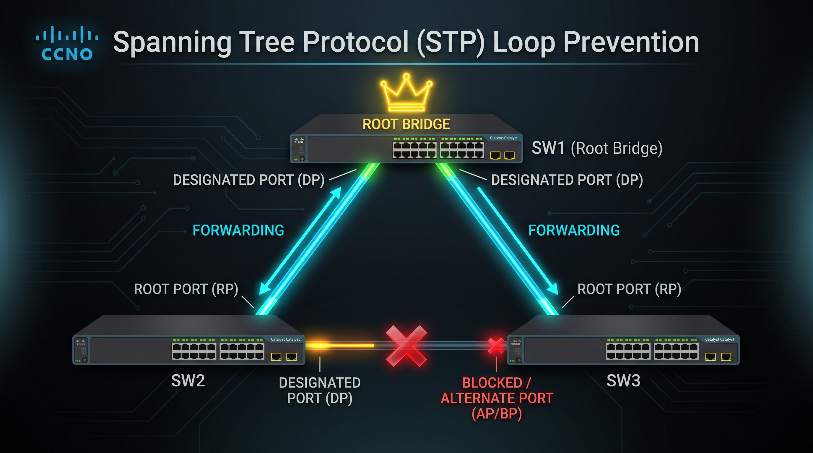
🛠️ Hands-On Cisco Packet Tracer Lab: Spanning Tree Protocol (STP)
Practice Root Bridge elections, designated/root port selection, and blocking state convergence directly inside Cisco Packet Tracer. Download the pre-built topology below: