What is a VLAN? A Beginner-to-Pro Guide
A Virtual Local Area Network (VLAN) is a networking technology that divides a single physical switch into multiple, isolated virtual switches at Layer 2.
In a standard, unconfigured switch—known as a flat network—every plugged-in host resides inside the exact same broadcast domain. When any single machine sends out broadcast messages (such as an ARP request), that packet floods every single port across the switch.
VLANs solve this problem by introducing logical segmentation, creating distinct broadcast domains without requiring separate hardware switches.
Why Do Networks Need VLANs?
- Eliminating Broadcast Storms: High volumes of broadcast traffic consume available bandwidth and waste endpoint CPU cycles. VLANs contain broadcast traffic exclusively within their assigned segment.
- Layer 2 Security & Isolation: By default, devices on different VLANs cannot intercept or send traffic to each other directly at Layer 2. For example, an accounting database in VLAN 30 is shielded from guest Wi-Fi devices in VLAN 50.
- Cost Efficiency: Instead of purchasing separate physical switches and pulling dedicated cables for individual teams (HR, Sales, Engineering), a single switch manages multiple secure departments.
- Simplified Management: When an employee moves desks, network administrators simply reassign the switch port's VLAN ID instead of physically recabling the patch panel.
Access Ports vs. Trunk Ports
When configuring VLANs, switch interfaces operate in one of two primary modes:
| Port Mode | Purpose | 802.1Q Tagging? | Typical Connection |
|---|---|---|---|
| Access Port | Carries traffic for only one VLAN. | No (Untagged). End hosts only receive standard Ethernet frames. | PCs, Printers, IP Phones |
| Trunk Port | Carries traffic for multiple VLANs over a single cable. | Yes (Tagged). Inserts an IEEE 802.1Q header into the frame. | Switch-to-Switch or Switch-to-Router |
How IEEE 802.1Q Frame Tagging Works
When an Ethernet frame leaves an access port and traverses a trunk link, the switch inserts a 4-byte (32-bit) tag into the header. This tag contains a 12-bit VLAN ID (VID) field, which supports VLAN numbers ranging from 1 to 4094. Once the frame reaches the remote switch, the tag is inspected, stripped off, and forwarded directly to the correct destination access port.
How Devices in Different VLANs Communicate
Because VLANs strictly divide Layer 2 broadcast domains, devices on different VLANs cannot talk to each other without a Layer 3 routing engine.
To enable Inter-VLAN communication, networks rely on two main methods:
- Router-on-a-Stick (ROAS): A router connects to the switch via a single 802.1Q trunk link, using virtual sub-interfaces (e.g.,
G0/0/0.10,G0/0/0.20) to serve as default gateways. - Multilayer Switching (SVIs): A Layer 3 switch performs routing internally at wire speed using Switched Virtual Interfaces (e.g.,
interface vlan 10), eliminating the need for an external router.
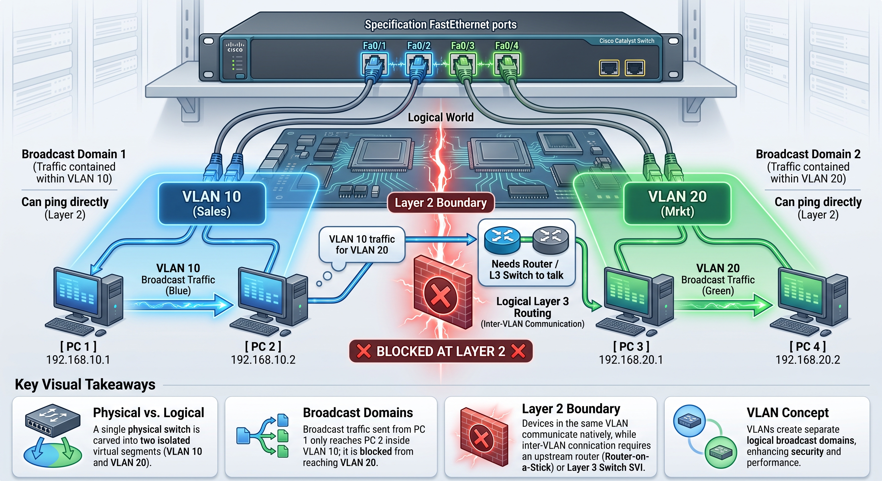
Network Segmentation Diagram
                +-----------------------------------------+
                |         Physical Cisco Switch           |
                |                                         |
                |  [ Fa0/1 ]   [ Fa0/2 ]   [ Fa0/3 ]   [ Fa0/4 ]  |
                +-----+-----------+-----------+-----------+-------+
                      |           |           |           |
      ================|===========|===========|===========|================
      LOGICAL VLANs:  |           |           |           |
                      v           v           v           v
                +-----------+-----------+-----------+-----------+
                |   VLAN 10 |  VLAN 10  |  VLAN 20  |  VLAN 20  |
                |  (Sales)  |  (Sales)  |  (Mrkt)   |  (Mrkt)   |
                +-----------+-----------+-----------+-----------+
                      |           |           |           |
                      v           v           v           v
                   [ PC 1 ]    [ PC 2 ]    [ PC 3 ]    [ PC 4 ]
                 192.168.10.1 192.168.10.2 192.168.20.1 192.168.20.2
                      \___________/               \___________/
                            |                           |
                     Broadcast Domain 1          Broadcast Domain 2
                     (Can ping directly)         (Can ping directly)
                            \                           /
                             \                         /
                              ❌ BLOCKED AT LAYER 2 ❌
                       (Needs Router / L3 Switch to talk)
Video Tutorial
For an animated walkthrough showing broadcast domains, trunking, and frame tagging, watch the How VLANs Work Complete Tutorial.
🛠️ Hands-On Cisco Packet Tracer Lab Files
Practice creating VLANs, assigning access ports, and configuring 802.1Q trunk links: